¶ GM Modules
The GM 7 /8 pin modules have been used in a wide variety of GM engines from 4 cylinder to V8s (small and big block). The 8 pin distributor was also widely used in marine applications by Indmar, Mercruiser, and others.
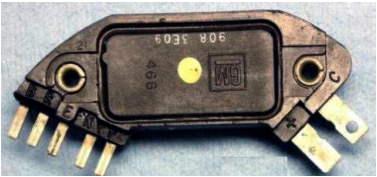
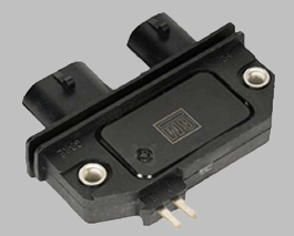
The 7 and 8 pin modules are functionally equivalent and largely share the same wiring. The 7 pin is used in the large coil-in-cap distributors while the 8 pin is used in the small cap distributors with remote mounted coils. The 8 pin has one additional terminal that provides a sensor ground. Both modules provide coil ground via the metal grommets used to secure them to the distributor.
These modules provide an simple means for computer controlled timing while retaining the distributor. They were designed to be used with throttle body injection and port injection motors and provide automatic coil current limiting (7.5 amps was the GM specification) and automatic dwell control. The can be adapted to other distributor applications that use either variable reluctor or hall type sensors.
¶ Pin Descriptions and connections
• "+" : Battery voltage from a switched ignition source. Provides the power to operate the module.
• "C-" : Ignition coil negative connection.
• "P & N" : Positive and Negative of the distributor reluctor. Polarity is important. GM distributor connectors can only be connected one way. For use with other distributors, verify polarity of the reluctor leads.
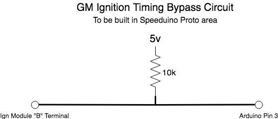
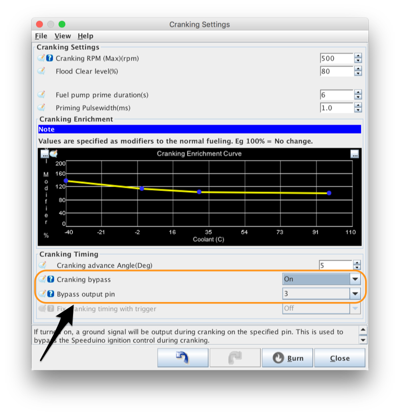
• "B" : Ignition bypass. When cranking, grounding this line bypasses computer control of timing. The timing iscontrolled by the module only. This can be done using the Speeduino Cranking Bypass pin function (see below).
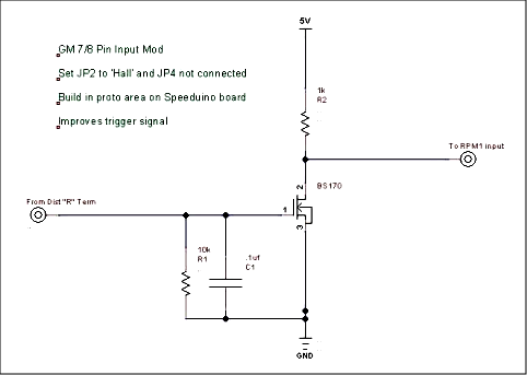
• "R" : Reference or tach signal. This outputs a 5 volt square wave that serves as the RPM1 input for the Speeduino. To use this, connect it to RPM1 and set JP2 to Hall and JP4 connected (ie, 5 volt pull up).
• "E" : Timing control signal. When pin B has 5 volts on it, the module allows Speeduino to control the timing using this pin. The output of Ign1 should be connected to this pin.
• "G": (8 pin only) Signal ground. Should be connected to the Speeduino sensor ground. (Module ground is provided through the metal mounting grommets)
A timing bypass circuit must be constructed to utilize the Speeduino ignition timing control. The small circuit below should be built in the proto area.
