¶ AFR/O2 (Closed loop fuel)
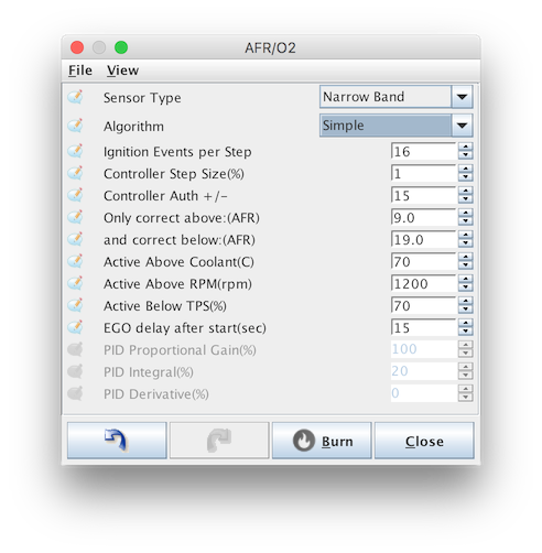
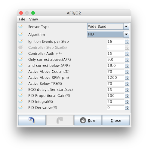
AFR/O2 (for Air:Fuel Ratio), dialog controls the closed loop fuel control, used for adjusting injector load based on input from an exhaust oxygen sensor (O2 sensor). In conjunction with the AFR Table, the closed loop AFR system will compare the actual O2 reading with the current target fuel ratio and make adjustments accordingly.
Use of a wideband sensor and controller is strongly recommended, however basic functionality is possible with a narrowband sensor if this is not available.
Note that closed loop fuel control is not a replacement for a poor tune. Many good configurations do not used closed loop control at all or only allow it very small adjustment authority.
¶ Settings
Speeduino supports 2 closed loop algorithms, each intended for different configurations:
- Simple - A time based 'target chasing' algorithm where the amount of fuel adjustment is dependant on how long the reading has been lean or rich compared to the current target. This algorithm is best suited to narrowband sensors where only basic rich/lean information is available. In particular, this algorithm performs poorly if you have a fuel map that is not close to complete. If you have this enabled and are seeing oscillations in the pulse width and/or AFRs, even when cruising, then you should disabled closed loop control until the base fuel MAP is better tuned.
- PID - This is the preferred closed loop algorithm and will provide better results when combined with a wideband sensor and tuned correctly.
¶ Common variables

- Sensor type - Narrowband or wideband, depending on hardware configuration. Narrowband sensor should be of the 0-1v type, wideband sensors should have a 0-5v signal. Wideband sensors need to be calibrated in the Tools->Calibrate AFR Table dialog
- Algorithm - See above for description of each algorithm available
- Ignition events per step - The AFR adjustment calculation will be performed every this many ignition cycles. Changes to closed loop adjustment typically have some lag before their impact is registered by the O2 sensor and increasing this value can take this lag into account. Typical values are 2-5.
- Controller step size -
- Controller Auth - The maximum % that the pulse width can be changed through this closed loop adjustment. Recommended value is no more than 20%.
- Correct above/below AFR - The AFR range that closed loop adjustments will be applied within. This range is typically limited by the sensor and controller in use.
- Active above Coolant - Closed loop should only operate once engine is up to operating temperature. This value should be set to match the engines standard operating temp.
- Active above RPM - Closed loop adjustments should genrally not be made at idle. Use this value to specify when adjustment should begin being made.
- Active below TPS - Above this TPS value, closed loops adjustments will be disabled
- EGO delay after start - All O2 sensors require a warmup period before their readings are valid. This varies based on the sensor in use, but 15s is a safe value in most cases.
¶ PID only variables

- P/I/D - PID Proportional Gain, Integral and Derivative percentages.
These options are in addition to the Simple conditions and specify the parameters of the closed loop operation