¶ Variable Valve Timing (VVT)
Speeduino has an on board VVT controller than can be used to regulate one or two camshafts. VVT output can adjust valve timing or lift usually by controlling solenoid that uses oil pressure to change cam timing/lift.
Supported VVT modes are On/Off, open loop PWM and closed loop PWM.
¶ VVT modes
¶ On/Off
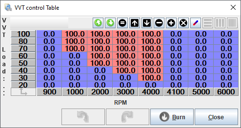
In On/Off mode the VVT output is either On or Off depending on the load and RPM. This is suitable control mode for simple VVT systems in older engines. MAP or TPS can be selected as load source. VVT control table is used to define when VVT output is on or off. Value 100 on the table defines that output is on and any other value sets the output off. For simplicity it's recommended to use values 100 and 0 in the VVT control table to represent on and off (0% duty and 100% duty). This mode can be used for example in BMW single vanos engines and Honda VTEC engines.
¶ Open loop PWM
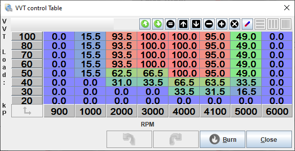
In Open loop PWM mode the VVT output uses Pulse Width Modulation to adjust the cam timing. MAP or TPS can be selected as load source and also output frequency is selectable. Output duty is defined by the VVT control table so that value on the map is directly the VVT output duty. VVT output has 0.5% duty accuracy and the available frequency range is 10-510Hz
¶ Closed loop PWM
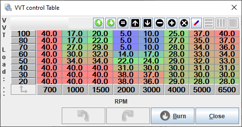
Closed loop PWM mode also uses Pulse Width Modulation for VVT output to adjust the cam timing. But in this mode the VVT control table is used as cam angle target table. VVT control algorithm uses PID loop to keep the cam angle at the target value using the VVT output duty. Setting up the closed loop VVT is way more in depth than On/Off or Open Loop modes. But yields to better cam control if the engine supports this kind of VVT mode. This mode can be used for example in BMW dual vanos engines and Ford ST170.
Note: Currently Closed loop VVT control is experimental feature and it only works for Miata, Missing tooth and ST170 trigger patterns.
¶ Settings

¶ General
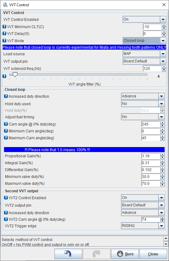
- VVT Control Enabled - If VVT isn't used, set this to Off.
- VVT Minimum CLT(C) - Minimum coolant temp to activate VVT.
- VVT Delay(S) - Time to wait after reaching minimum coolant temp (additional time for oil warmup).
- VVT Mode - For selecting one of the three VVT modes.
- Load source - This defines the Y-axis (Load axis) of the VVT control table. Available options for load are MAP and TPS.
- VVT output pin - For selecting VVT output pin. "Board default" uses the VVT output pin specific for your board and it's the correct setting for most of the setups. But also other pins for VVT output are available.
- VVT Solenoid freq.(Hz) - This sets the VVT output frequency. Available frequency range is 10-510Hz.
- VVT angle filter (%) - Adjustable filter for cam angle reading. Start with low filter values from 2 to 10, and increase filtering amount if the cam angle reading is noisy. The cam angle reading works in all three VVT modes if the trigger patterns also supports closed loop VVT.
¶ Closed loop
- Increased duty direction - Sets the closed loop control direction. If higher solenoid duty advances cam, set this to "Advance". If on the other hand, more duty retards the cam, set this to "Retard".
- Hold duty used - In some VVT systems, specific solenoid duty is used to hold the current cam angle. Use this setting to enable the hold duty.
- Hold duty (%) - Set the desired cam angle holding duty. Usually around 50%.
- Adjust fuel timing - By enabling this, fuel injection timing is adjusted based on the cam angle.
- Cam angle @ 0% duty(deg) - This setting is used to bring the cam angle reading to usable 1-99 degrees range. First use Open Loop mode to figure out the cam angle reading at 0% duty and then switch to closed loop and write the open Loop 0% duty cam angle reading here. When doing that, the cam angle reading at 0% duty will show 0. Now you can fine tune this value so that the VVT angle reading is in the 1-99 range. You might need to adjust this value bigger amount if the cam angle reading goes to negative values when duty increases. For example if 100% cam angle reading is -35, lower this value at least by 36. So that the both ends of the adjustment are withing the 1-99 range. Also make sure that the cam angle readings stay withing the 1-99 range at higher RPM too. Belt strecth etc. can affect the cam angle reading, even though duty stays the same.
- Minimum Cam angle(deg) - Safety limit for minimum expected cam angle value. If cam angle gets smaller or equal to this, it triggers VVT error state, closed loop adjustment is disabled and VVT output duty drops to 0%. Start by using 0 degrees and fine tune if needed.
- Maximum Cam angle(deg) - Safety limit for maximum expected cam angle value. If cam angle gets bigger than this, it triggers VVT error state, closed loop adjustment is disabled and VVT output duty drops to 0%. Start by using 100 degrees and after everything is dialed in, set this to slightly higher value than the biggest cam angle reading is in your setup.
¶ Second VVT Output
- VVT2 Control Enabled - To enable second VVT control. This uses mainly the same settings as the primary VVT control. For the settings that are available for VVT2, see descriptions above. Set this to Off if not used.
Note: Currently Closed loop VVT control for second VVT output is only available for missing tooth trigger pattern with single tooth on the cam.
- VVT2 Trigger edge - Set the second cam input to trigger on falling or rising edge.
¶ VVT duty cycle
The VVT control table function varies depending on whether on/off, open or closed loop VVT mode has been selected.
- In On/Off mode, 100 is taken as "output on" and any other values represents "output off". Values 0 and 100 are recommended to use in this mode.

- In open loop mode, the map values are the duty cycle percents that will be used

- In closed loop mode, this map serves as a cam angle target table.
