¶ V0.3 Board
¶ Overview
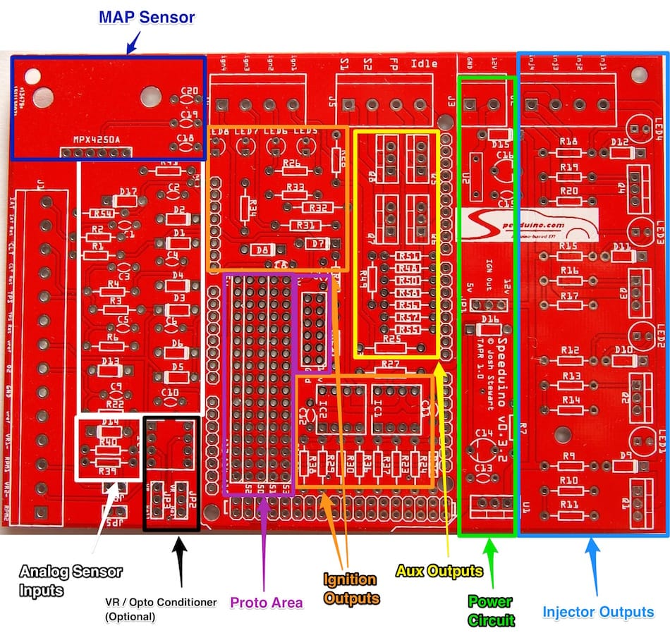
The v0.3 board was the first widely available Speeduino shield and is suitable for many typical 1-4 cylinder injection and ignition applications (Excluding direct injected engines). It uses screw terminals for all connections in order to make test wiring simple and quick for prototyping.
¶ Board Features
The v0.3 boards includes the following features:
- 4 injector channels
- 4 Ignition outputs
- Fully protected input channels for CLT, IAT, TPS and O2
- Optional VR conditioner mount on crank and cam inputs
- MAP sensor mount location
- 4 medium current spare outputs (Eg Fuel pump, thermo fan etc)
- All I/O through screw terminals on the board
- Proto area with IO, SPI and power breakouts.
¶ Physical Layout

¶ Proto area
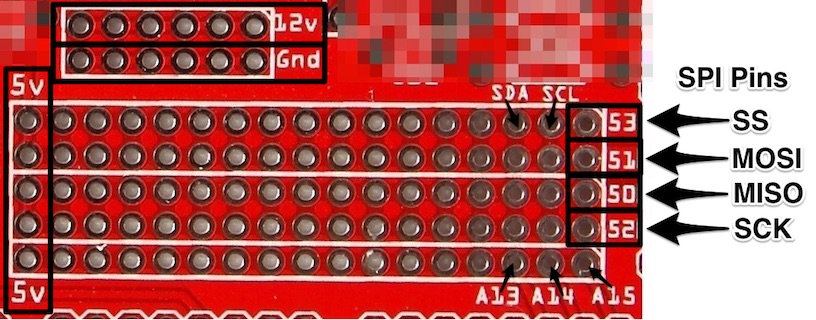
The proto area can be used for adding your own circuits on to Speeduino if required or simply as a convenient access point to various connections. The connections broken out to the proto board are:
- 5v and 12v
- Grounds
- SPI pins (MOSI, MISO, SCK and SS). Alternatively these can be used as generic digital IO (Arduino pins 50-53)
- 3 generic analog inputs (13-15)

¶ Board Assembly
Refer to the Board revisions for a link to the Bill of Materials (BOM) of your specific board.
Assembly of a complete board is relatively straightforward with all components being through hole and labelled on the board (See above mentioned BoM for parts list). Whilst it does not matter which order components are installed, the following is recommended for simplicity:
- All resistors
- All diodes (Including LEDS)
- All capacitors
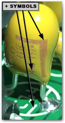
- Take note that C14 and C16 are polarised capacitors, meaning that they must be put in the correct way around. The capacitors should be marked with a + sign on one side. On the PCB, the positive side is indicated by a line on the capacitor symbol.

Correct capacitor orientation
4. All jumper headers (JP*)
5. Arduino pins:
- Suggested method: Break header pins into required lengths and insert into an Arduino Mega. Place the board over the top of the pins and solder in place
- Note that not all the pins on the end double row need to be populated (Though there's no harm in doing so). The odd numbered pins (Eg D23, D25 .. DD53) do not need pins on them.
- IC sockets
- MAP sensor (If used)
- NOTE: ALL self assembly boards have the MAP sensor with the hole at the top.
- All screw terminals
- All MOSFETs
- Power regulator
¶ Assembly Instruction video
v0.4 assembly video available at YouTube
¶ Board Configuration
The board can be configured in multiple ways depending on the hardware you use and way your setup is configured.
¶ Board default outputs
Multiple functions within Speeduino have adjustable outputs or can be set to Board Default. The following are the Default pin outs for the v0.3
Note: These defaults are applicable to the Jan 2017 firmware and newer
| Function | Board output | Arduino pin |
|---|---|---|
| Boost control | S2 Screw terminal | 7 |
| VVT | S1 Screw terminal | 6 |
| Idle 1 | Idle Screw terminal | 5 |
| Idle 2 (3 wire idle valves) | Proto area (Labelled 53) | 53 |
| Fuel pump | FP Screw terminal | 4 |
| Launch/Clutch | Proto area (Labelled 51) | 51 |
¶ Optional Components
If using a VR crank sensor, the board will require the addition of a VR conditioner. The board has been designed to work with the dual VR conditioner from JBPerf (http://www.jbperf.com/dual_VR/index.html) which will plug directly in. Other VR conditioners will also likely work, but have not been tested. There is now also an official VR board that can be used, see link on the left.
¶ SP721 Over-voltage Protection
For users having difficulty obtaining the SP721 used in some versions, see info on the SP721 Diode Alternate page.
¶ Jumper Configuration
Depending on the type of crank and cam sensors you have, there are a number of jumpers that will need to be set. The jumpers that need setting are:
- JP1 - This sets whether the Ignition outputs are 12v or 5v. Note that even if you set this to 12v you should **NOT** connect these directly to a high current coil. These outputs should only ever go to a logic level coil or an igniter
- JP2 - Whether or not the RPM1 (Crank) input should be routed via the (Optional) VR conditioner. This should be set to VR when using either a VR sensor or a hall sensor that switches between 0v-12v
- JP3 - Same as JP2, but for the RPM2 (Cam) input
- JP4 - 10k pullup resistor for RPM1 input. Should be jumpered ('On') when a sensor is used that switches between ground and floating (Which is most hall effect sensors)
- JP5 - Same as JP4, but for the RPM2 (Cam) input
To make this simpler, the most common sensor types and their required configurations are below:
| Crank Sensor | Cam Sensor | JP2 | JP3 | JP4 | JP5 |
|---|---|---|---|---|---|
| Hall sensor | - | Hall | Off | On | Off |
| VR Sensor | - | VR | Off | Off | Off |
| 0v-12v Hall Sensor (Requires VR Conditioner) | - | VR | Off | Off | Off |
| Hall sensor | Floating Hall sensor | Hall | Hall | On | On |
| VR Sensor | Floating Hall sensor | VR | Hall | Off | On |
¶ Board revisions
| Version | Changes | BOM |
|---|---|---|
| V0.3.7 | Added bluetooth header | Same as v0.3.6 |
| V0.3.6 | Added filter caps to both crank and cam inputs | Download |
| V0.3.5 | Added flex fuel input to proto area. Many routing improvements. | Download |
| V0.3.4 | Routing cleanup and more useful silkscreening | Same as v0.3.3 |
| V0.3.3 | Replaced diode array with SP721 | Download |
| V0.3.2 | Added Proto area. Removed spare IC socket (Had not been used) | Download |
| V0.3.1 | Moved MAP sensor closer to edge of board. Beefier routing on the high current outputs (Including injectors) | Download |
| V0.3 | Initial release | Download |
Github for the 0.3 hardware designs: https://github.com/speeduino/Hardware/tree/main/v0.3
¶ Full pin number chart
Chart consist all pin numbers used in Speeduino Firmware for v0.3 boards. Pin numbers are Arduino Mega pin numbers. Not IDC pin numbers. This chart can be used as a guide when setting unused default outputs for some other use.
| Pin name | Pin number | Description |
|---|---|---|
| pinInjector1 | 8 | Output pin injector 1 |
| pinInjector2 | 9 | Output pin injector 2 |
| pinInjector3 | 10 | Output pin injector 3 |
| pinInjector4 | 11 | Output pin injector 4 |
| pinInjector5 | 12 | Output pin injector 5 |
| pinCoil1 | 28 | Pin for coil 1 |
| pinCoil2 | 24 | Pin for coil 2 |
| pinCoil3 | 40 | Pin for coil 3 |
| pinCoil4 | 36 | Pin for coil 4 |
| pinCoil5 | 34 | Pin for coil 5 (PLACEHOLDER) |
| pinTrigger | 19 | The CAS pin |
| pinTrigger2 | 18 | The Cam Sensor pin |
| pinTrigger3 | 3 | The Cam sensor 2 pin (VVT2 input pin) |
| pinTPS | A2 | TPS input pin |
| pinMAP | A3 | MAP sensor pin |
| pinIAT | A0 | IAT sensor pin |
| pinCLT | A1 | CLS sensor pin |
| pinO2 | A8 | O2 Sensor pin |
| pinBat | A4 | Battery reference voltage pin |
| pinDisplayReset | 48 | OLED reset pin |
| pinTachOut | 49 | Tacho output pin |
| pinIdle1 | 5 | Single wire idle control |
| pinIdle2 | 53 | 2 wire idle control |
| pinBoost | 7 | Boost control |
| pinVVT_1 | 6 | Default VVT output |
| pinVVT_2 | 48 | Default VVT2 output |
| pinFuelPump | 4 | Fuel pump output |
| pinStepperDir | 16 | Direction pin for DRV8825 driver |
| pinStepperStep | 17 | Step pin for DRV8825 driver |
| pinStepperEnable | 26 | Enable pin for DRV8825 |
| pinFan | A13 | Pin for the fan output |
| pinLaunch | 51 | Can be overwritten below |
| pinFlex | 2 | Flex sensor (Must be external interrupt enabled) |
| pinResetControl | 50 | Reset control output |