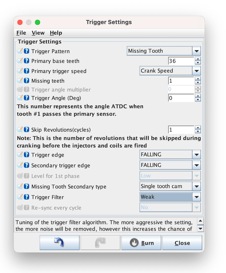
¶ Trigger Setup
¶ Overview
One of the most critical components of an EFI setup is the Crank Angle Sensor (CAS) and how it is used by the ECU. The Trigger settings dialog is where the trigger configuration is defined and it is vitally important to have this correct before trying to start your engine.
With incorrect settings, you may have issues getting sync or see erratic RPM readings.
Note that many of the settings on this dialog are dependant on your configuration and it is therefore normal that some options maybe greyed out.
¶ Trigger Settings

-
Trigger Pattern - The pattern used by the crank/cam sensor setup on your engine. For a full list of the supported patterns, see the Decoders page
-
Primary Base teeth - For patterns where the number of teeth are variable (missing tooth, dual wheel etc), this number represents the number of teeth on the primary wheel. For missing tooth type wheels, this number should be the count as if there were no teeth missing.
-
Primary trigger speed - The speed at which the primary input spins. It is closely related to the Primary Base teeth setting and indicates whether that number of teeth passes the sensor once every crank revolution or every cam revolution.
-
Missing teeth - If using the missing tooth pattern, this is the size of the gap, given in 'missing teeth'. Eg 36-1 has 1 missing tooth. 60-2 has 2 missing teeth etc. The missing teeth MUST be all located in a single block, there cannot be multiple missing tooth gaps around the wheel.
-
Trigger angle multiplier - This option is used only on the Non-360 pattern.
-
Trigger angle - The angle of the crank, After Top Dead Centre (ATDC), when tooth #1 passes the sensor on the primary (crank) input. This setting is critical for Speeduino to accurately know the current crank angle. See section below ('Finding tooth #1 and trigger angle') for further information on how to determine this value. You should be using a timing light to confirm angle is correct once calculated. Without doing this your angle may be incorrect.
-
Skip revolutions - The number of revolutions the engine should perform before the Sync flag is set. This can help prevent false sync events when cranking. Typical values are from 0 to 2
-
Trigger edge - Whether the primary signal triggers on the Rising or Falling edge.
- VR Conditioners require specific setting depending on model used:
- VR conditioners based on MAX9926 or LM ICs should use
RISING. This includes Dropbear units - DSC conditioners should use
FALLING
- VR conditioners based on MAX9926 or LM ICs should use
- VR Conditioners require specific setting depending on model used:
-
Secondary trigger edge - Whether the secondary signal triggers on the Rising or Falling edge
-
Missing Tooth Secondary type - Cam mode/type also known as Secondary Trigger Pattern.
-
Level for 1st phase - Only active with "Poll level" cam decoder. The level of the cam trigger input will be checked at crank tooth #1 and this defines if the level is supposed to be High or Low at 1st phase of the engine.
-
Trigger filter - A time based software filter that will ignore crank/cam inputs if they arrive sooner than expected based on the current RPM. The more aggressive the filter, the closer to the expected time the filter will operate. Higher levels of filtering may cause true pulses to be filtered out however, so it is recommended to use the lowest setting possible
-
Re-sync every cycle - If set to yes, the system will look for the sync conditions every cycle rather than just counting the expected number of teeth. It is recommended that this option should be turned on, however if you have a noisy crank/cam signal you may need to turn it off as it can cause sync to drop out occassionally. Once Speeduino has full sync it will continue to run in full sequential mode unless sync loss on crack trigger occurs.
¶ Finding tooth #1 and trigger angle
Please refer to the Trigger Patterns and Decoders for the trigger that you are using