¶ Hardware Requirements overview
This page presents the basic hardware requirements of a Speeduino system, as well as a number of options for different variations of these. It does not represent every supported combination of hardware, but provides an overview if you're starting out.
¶ Arduino
Most of the Speeduino designs use the Arduino Mega 2560 R3 as the controller. All official and most clone Arduino Mega 2560 boards will work fine, but it is recommended to use a board that has the 16u2 serial interface rather than the cheaper CH340. Which chip a board uses can usually be found on the information/specification listing from most retailers, but if in doubt, ask the seller you are looking to buy from.
¶ Inputs
¶ Crank sensor / Camshaft Sensor
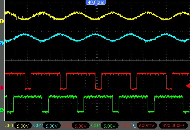
This is arguably the most important sensor for Speeduino to function correctly. The signal going to the Arduino must be a 0v-5v square wave series of pulses (shown below) representing teeth on a wheel running at crank (or cam) speed. Many Hall and 'opto' sensors meet this digital square-wave spec. If only a crankshaft trigger wheel is used (no cam signal), the crank wheel must have a 'missing' tooth in order to provide position information as well as the engine RPM. Tested missing-tooth wheels currently are 4-1, 12-1, 36-1 and 60-2.
For all timing signal parsing options see the Trigger Patterns and Decoders page.
Alternatively (and necessary for full-sequential injection) an added cam signal with or without crank wheel missing teeth. These setups are indicated by the added "/x", such as 60-2/1, for a 60-tooth crank wheel, with 2 missing teeth, and a 1-tooth cam signal per cycle. Cam-speed missing-tooth wheels can also support semi and full-sequential.
VR (variable reluctance) sensors can also be used, however as the board does not contain any sort of signal conditioner to convert the sine wave (below) to the required square wave, an additional module will be needed. An 8-pin DIP socket is located on v0.3.x and v0.4.x series official boards for this purpose as IC3. The MAX9926 chip has been tested to work with most types of input signals, and is available from the Speeduino Store, however any similar module that outputs a 0v-5v square wave (LM1815, LM358, SSC/DSC, many OEM modules, etc.) should also work fine with VR sensor signals.
VR conditioners need to have Trigger Edge in TunerStudio set to the correct option based on the conditioner you are using. Rising for MAX or LM conditioners, and Falling for DSC and most others.

It is recomended to take precautions for EMI while routing and choosing the wire for the crankshaft and camshaft sensors. Keeping wires away from electrically noisy components like the alternator, and spark plugs can help. Using a shielded cable can also help (tie the shield to the ECU side only). Software filtering can be used but nothing beats a clean signal from the source.
If crank / cam signal is lost and EMI / filtering options have been exhaused, ensure that the Speeduino board's +12V and GND connections are noise free as well. It is possible for noise on the main power rail to cause interference.
¶ TPS
TPS sensor must be of the 3 wire potentiometer type, rather than the 2 wire on/off switches found on some throttles. If your TPS is a 3 wire sensor then it will likely work, however you will need to confirm it is a potentiometer (variable) type sensor.
The TPS functions by sending an analog variable voltage signal to Speeduino in order to report the current position of the throttle. It is typically supplied with V+ of 5V and ground (GND, signal ground, or signal return), routing through an internal potentiometer to output a low voltage at low throttle opening, and a rising voltage with greater throttle opening.
If using a TPS with unknown connections; it is recommended to test the TPS with an ohm meter in order to determine the connection of each pin without risking damage by applying sensor power randomly. This can be accomplished on the bench or with the engine off and TPS disconnected:
- Assign a letter to each pin.
- Attach the ohm meter to two pins, and operate the throttle from closed (idle) to wide-open (WOT), recording the results.
- Find the pair of pins where the resistance does not change significantly from idle to WOT. These are your two power pins.
- The remaining pin is your Signal pin.
- In order to determine which power pin is V+ and which is GND, test ohms between the Signal pin and one power pin.
- In idle position; if ohms are low that power pin is GND. If ohms are high that power pin is V+.
Most usable TPS sensors have 3 pins. If your TPS has a different number of pins, referring to the original engine wiring diagram may show the function, and whether it is usable or which pins to use for Speeduino. For TP sensors that work 'backwards', and wiring cannot be changed, a simple code modification is available on the Forums to make use of this type of TPS.
¶ MAP (Manifold Pressure)
The recommended MAP sensor is the MPX4250 from Freescale and this is integrated onto most Speeduino boards. This sensor supports readings up to 250kPa (1.5 bar or approx. 20psi of boost) and is a good midrange sensor for both NA and boosted applications running low to medium amounts of boost.
Other MAP sensors however are supported and any 0-5v sensor will work. If you want to use one that is not included in the list (Under Tools->Map Calibration in TunerStudio) then please make a new thread in the forum requesting this. Other sensors can and will work just fine, but you will need to calibrate these within TunerStudio against a different set of values. MAF IS NOT SUPPORTED.
¶ Temperature Sensors (CLT and IAT)
Any standard 2-wire thermistor sensor can be used for these temperature functions. The sensors have 1 side connected to a ground (Preferably from the ECU) and the other running to the signal line. These sensors have no polarity, so the orientation of these wires does not matter.
For full details, please see the Sensor Calibration page
¶ Exhaust Gas Oxygen Sensors (O2 and WBO2)
The type of O2 sensor (narrow or wide-band) must be selected in TunerStudio under Tools > Calibrate AFR Table.
¶ Narrow-band
NBO2 sensor signals are read directly by Speeduino. TunerStudio applies the standard non-linear 0-volt to 1-volt values for all standard NBO2 sensors automatically under calibration. Once set in calibration, Speeduino will use the designated NBO2 to adjust fueling according to the entries you make in the AFR table (Tuning > AFR Table), and the sensor is selected for type and parameters (or disabled) under Tuning > AFR/O2. Note that narrow-band sensors were originally designed to target stoichiometric AFR (Lambda 1.0) for efficient catalytic emissions control, and are generally not sufficiently accurate or suitable for tuning efficient lean economy or rich power fueling. While not recommended; involved tuning methods are available to allow limited and approximate tuning for lean and rich AFRs using a NBO2 sensor.
¶ Wide-band
Wide-band oxygen (WBO2) sensors can detect and report a wider range of lambda (ƛ) or AFRs than narrow-band, and with greater accuracy, from approximately 10:1 to 20:1 (about 0.7 to 1.3 lambda), depending on specific sensor version and controller. Speeduino cannot use WBO2 sensors directly, requiring an external controller to process the signal and to apply sensor heating control. Enter the controller brand and model from the list displayed. If the controller signal is generic linear or custom, select and enter the required information, or an option to install a custom INC file is available in the menu list.
Once set in Tools > Calibrate AFR Sensor, Speeduino can use the designated WBO2 to report lambda/AFR to TunerStudio for gauge display. After the sensor is selected for type and parameters under Tuning > AFR/O2 it can adjust corrective fueling on-the-fly according to the entries you make in the AFR table (Tuning > AFR Table), and for auto-tuning in TunerStudio, or MegaLogViewer in real-time or from logs. Settings also include the option to disable. Although Speeduino can use the WBO2 information to correct fueling; it is strongly suggested it not be used to compensate for poor tuning.
¶ Application-Specific Inputs
Circuits and techniques Speeduino users have found useful for adapting or implementing certain inputs or functions.
¶ Flex Fuel Sensor
See the Flex Fuel section for details on hardware and configuration of flex fuel setups.
¶ 12V Input Signal
Some position sensors output a 12v signal. To correct this, and avoid damaging the Arduino, a circuit like the one in the diagram can be constructed. The resistor R1 is not always required, but will make sure that any output that is not high is pulled low. Along with this circuit use the pull-up jumper on the Speeduino. This will effectively change a 0v/12v into a 0v/5v signal.
Many thanks to PSIG for the info and diagram.
¶ GM 7 / 8 pin Distributor Module
See GM_Module for more details
¶ Outputs
See the links to wiring diagrams in the menu for details about how each of these outputs should be wired.
¶ Injectors
Speeduino injector drivers use on/off (not PWM) control and are designed to work with "High-Z" injectors. This type of injectors are also known as "saturated" or "high-impedance" that use full battery voltage to control the injector open cycle, and generally the impedance is greater than about 8 Ohms. If you are running "Low-Z" ("peak and hold" or PWM-controlled) injectors that are lower impedance, you will need to install series resistors on these to avoid damaging the board with excessive current. The resistor ohms and watt rating can be calculated by Ohm's Law, or use an Internet calculator page such as the Speeduino Injector Resistor Calculator.
Speeduino can drive up to 2 High-Z injectors per output channel.
The 0.4v boards have 2 pins per injector channel allowing each injector to be directly connected to the board without splicing in the harness. If the application has less than 4 injectors using any pin connected to the proper channel will work.
¶ Coils
Current versions of the Speeduino use low-power output signals, designed to work with external small-signal ignition coil drivers, whether a separate type (module or ICM, igniter, IGBT, etc.), or built into the coil assembly ('smart' coils). This method permits Speeduino to have great flexibility to control most types of ignition systems. Attaching the Speeduino outputs directly to a traditional high current passive ("dumb" or 2-pin) ignition coil without an ignition coil driver WILL cause damage to your Arduino.
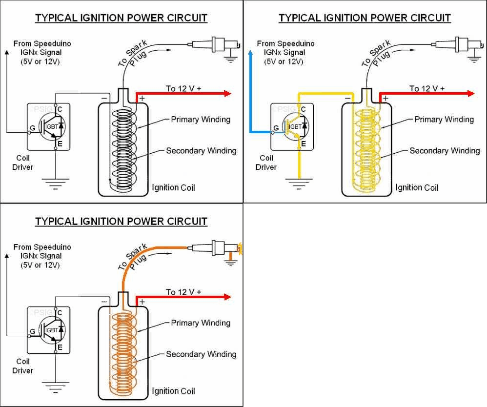
How Speeduino controls ignition circuit power In prior history, the coil driver was a set of mechanical contact points ("points"), simply replaced today by an electronic version. The added coil driver can be anywhere from inside the Speeduino to inside the coil assembly; though near or in the coil reduces electrical noise.
In the example animated image below, the Speeduino ignition signal is normally low (near ground or 0V) while Speeduino calculates the time to the next coil firing. At the proper time, Speeduino switches the ignition output to high (near 5V or 12V selectable) in order to switch the coil driver (example IGBT) on, allowing current to flow through the coil to ground. This is called the 'dwell' period. During dwell an increasing energy field is generated around the ignition coil core and wire windings.
At the end of the dwell period and therefore at the proper time for spark; Speeduino switches the coil driver off, stopping current flow, which collapses the energy field to create high voltage and the resulting spark:

In TunerStudio, the setting for this example would be to fire the spark "going low". The dwell setting is highly variable depending on coil type, voltage levels, etc. Too little dwell will give weak or no spark and excess dwell will rapidly increase heat, possibly damaging any of the ignition components, but usually the ignition coil or coil driver.
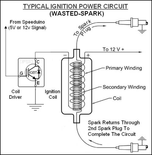
The wasted-spark version is below to show how it is identical in operation, but with the high-voltage spark returning through the second spark plug to complete the circuit:

A good run down of 'smart' coil types can be found at: http://www.megamanual.com/seq/coils.htm. There are many ignition modules available that Speeduino can use to control standard coils, or for smart coils you can generally use 4 or 5-pin types as these will always be logic level, although some 3-pin coils are also of this variety. GM LS1/2 coils are an example of powerful smart coils that are commonly used and can usually be obtained easily and cheaply.
(Note: In the past, some ignition control modules with current limiting or dwell control features (e.g., 1970s GM HEI, Bosch '024' types, and Ford DS1) were referred-to as "smart" modules. While still true, common terminology of individual ignition coils with at least a driver integrated, or newer technology with greater controls (e.g., controlled spark duration or multi-spark) are all considered "smart" coils. You must know the control requirements of the specific drivers, control modules, or coils you intend to use in order to operate them properly with Speeduino.)
¶ Aux Outputs
¶ Low Current
Most Speeduino versions have low-current (LC) signal outputs directly from the MEGA processor to (usually) the prototyping (proto) area of the board. These outputs are generally not suited to control power devices directly in this form, and need suitable output circuits built on the proto area to enable their use. Alternatively, the output functions such as Fuel Pump or Fan are re-assignable to other pins and components, such as the existing high-current (HC) output MOSFETs - see "Medium Current" section below for more.
Some Speeduino versions include an 8-channel ULN2803A Darlington transistor array IC that is capable of switching up to 1/2 amp per channel. These auxiliary outputs are sufficient to switch small devices directly, or to switch power-handling devices, such as power MOSFETs or automotive relays. Configuration and settings of these outputs is described in the Configuration section. Additional information for using a ULN2803A on v0.4-series boards may be found here. Similar output options and pin assignments may be used on other board designs.
¶ Medium Current
v0.3x and later boards include medium-power MOSFET auxiliary outputs to switch up to 3 amps directly. These are labeled "HC" in schematics and some references. These outputs are commonly used to operate idle valves, boost-control valves, VVT solenoids, etc., or to control relays for handling much larger loads, such as electric radiator fans. Configuration and settings of these outputs is described in the Configuration section.
¶ Auxilary IO
Speeduino has support for up to 16, 16bit external analog inputs via Serial3
¶ CAN bus
CAN bus is directly available for Speeduino in case of STM32 or Teensy MCU is used or via separate co-processor in case of mega2560. From the official boards Dropbear is only one currently featuring CAN bus and it uses Teensy 3.5 MCU. But there are 3rd party designs available too with CAN bus support. More information about Speeduino CAN bus support can be found here.
As Arduino mega2560 has no CAN bus interface a seperate "co-processor" interface has been designed. More information about this unit can be found here. This uses the functionality provided by the Serial3 port and connects via that port.
¶ Third Party Addon's
In This section you will find information about third party designed hardware designed to be used in conjunction with the Speeduino ECU
¶ GPIO for Speeduino
There are several variants of the GPIO , The firmware can be downloaded here
More information GPIO_for_Speeduino